guides
Spindle Sander Setup: Table, Sleeves, and Support
A successful spindle-sander setup connects several decisions: where the machine sits, how the work is supported, which sleeve assembly fits, and how dust is captured. Treat the model manual as the authority for installation order and permitted parts. Before installation, find the fastener instructions, electrical requirements, insert sizes, and clearances for your exact machine and configuration. Missing information in any of those areas needs resolving before the first run.
As an Amazon Associate I earn from qualifying purchases. How affiliate links work.
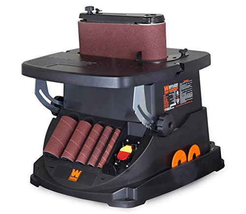 WEN 6524 Oscillating Belt and Spindle SanderCheck Amazon offer
 WEN 6510T 3.5 Amp Oscillating Spindle Sander,BlackCheck Amazon offer
Choose the location around the work
The machine's footprint is only part of its space requirement. A long blank may sweep through a wide area as a curved edge moves around the sleeve. A large cutout may require movement behind the spindle. Position the machine so the anticipated parts can travel without striking a wall, hose, or neighboring tool. Check lighting from the operator's usual position; glare can hide the layout line. A location that fits the machine tightly between other objects may be poor for the operation even though the base itself sits fully on the bench.
Establish a stable mounting arrangement
Use the mounting method approved for the machine and confirm that its supporting bench or stand is suitable. A portable board-mounted arrangement needs an appropriate way to secure it during use; the board alone does not prevent the assembly from moving. Consider the effort and handling involved if the tool will be stored between sessions. Do not improvise a precarious platform to gain height or clearance. The desired result is a repeatable working position in which ordinary sanding contact does not shift the machine or require the operator to steady the base.
Organize matched accessories
Lay out the required sleeve, drum, insert, and hardware while the machine remains disconnected. Confirm each item against the manual, particularly after buying a used tool or borrowing accessories from another machine. Similar-looking washers can differ in purpose, and an insert that leaves excessive space may create an avoidable opening around the abrasive. Keep complete sets labeled by their intended assembly. Compare the laid-out parts with the assembly diagram before installation; a missing washer is easier to identify there than after a sleeve fails to tighten.
Verify the table reference
Remove debris from the supporting surfaces and inspect the table and insert for damage. When a square edge is required, check the table relationship using a suitable measuring method with power isolated. If the table tilts, confirm its lock and the accuracy required by the actual project rather than trusting a scale automatically. Consider whether the workpiece itself provides a flat reference. A perfectly adjusted table cannot keep a warped blank from rocking. Make this distinction before changing machine alignment in response to a defect caused by an unstable workpiece.
Plan extraction and power together
Route the extraction hose so it cannot pull the machine, foul the moving blank, or create an awkward reach. Confirm compatibility with the machine and collector instructions. Likewise, check the specified power supply and any restrictions on extension cords. Keep cords out of the handling path and arrange access to the disconnect point. A setup should support both normal use and prompt isolation for adjustments. Do not regard a hose adapter that physically fits as proof of adequate airflow, or an available receptacle as proof that the electrical requirements have been met.
Finish with a documented first-use check
Complete the manufacturer's test-run procedure after installation. Before adding a workpiece, verify that the sleeve assembly operates normally and that no installation tools remain on the table. Record the model, revision, accessory dimensions, and any setup measurements relevant to your work. These notes are particularly valuable in shared shops or when the tool is repeatedly dismantled for storage. CCOHS directs users to understand the tool's instructions and limitations. A documented setup makes that understanding easier to preserve, while any unresolved abnormal behavior should be addressed before ordinary sanding begins.
Questions about Spindle Sander Setup: Table, Sleeves, and Support
Can I use a spindle sander without mounting it?
Follow the exact model’s mounting instructions. A stable-looking benchtop placement does not establish that the machine is secured appropriately.
Can I use the largest table insert for every sleeve?
Use the insert specified for the installed assembly. An unnecessarily large opening reduces support and can increase pinch hazards.
Should the table scale be trusted for precision angles?
Verify the angle required by the project with a suitable reference. A scale is a starting indication, not evidence of a finished part’s accuracy.